Project Title: Mechanical Gearbox and Linkage Mechanism – 3D CAD Design
Introduction
3D CAD Design is a key element of modern mechanical engineering, enabling engineers to visualize, analyze, and validate complex mechanisms before physical manufacturing. This project presents a detailed 3D CAD model of a mechanical gearbox and linkage system designed for efficient motion and force transmission.
Project Overview
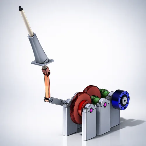
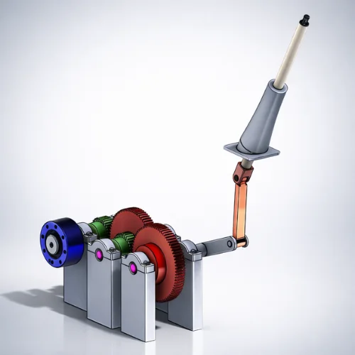
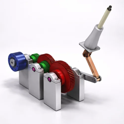
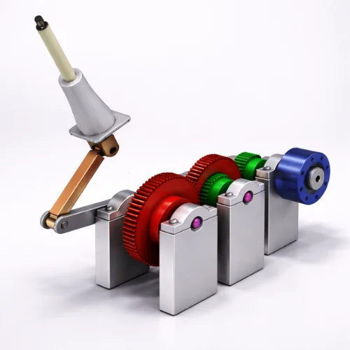
This project focuses on the complete 3D CAD design of a gear-driven mechanical linkage mechanism. The system consists of spur gears, shafts, bearings, support blocks, and a lever-based linkage assembly. The mechanism is designed to convert rotational motion into controlled linear and angular movement, ensuring smooth operation, durability, and ease of assembly.
Features and Specifications
- High-Precision Gear Design: Spur gears modeled with accurate tooth profiles for smooth meshing and efficient torque transmission.
- Mechanical Linkage System: Lever and rod mechanism designed to convert rotational motion into controlled linear movement.
- Shaft and Bearing Support: Properly aligned shafts supported by bearing housings to minimize friction and wear.
- Structural Stability: Rigid support blocks ensure alignment and strength under load conditions.
- Manufacturing Ready: Design optimized for CNC machining, milling, turning, and mechanical assembly.
Design Process
The design process begins with defining functional requirements for motion transfer and load handling. Individual components such as gears, shafts, bearings, and linkages are modeled with precise dimensions and tolerances. The complete assembly is then validated digitally to check gear meshing, motion range, and mechanical interference. Multiple design iterations are performed to improve strength, reliability, and manufacturability before final approval.